Engine · 993-ENG-CONNECTING-ROD-TI64-F0-0001
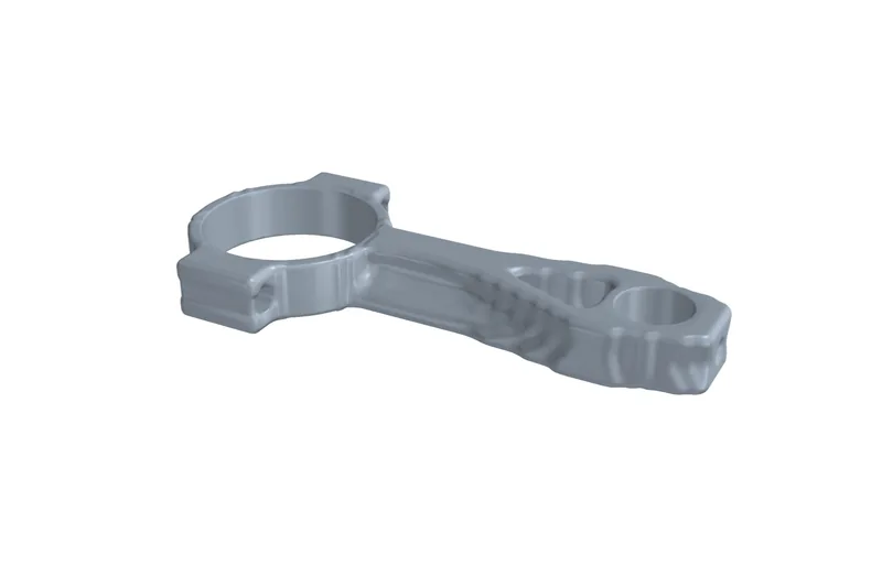
993/993 Turbo connecting rod, Ti64 F0 topology concept
ConceptNot authorised until engineering review
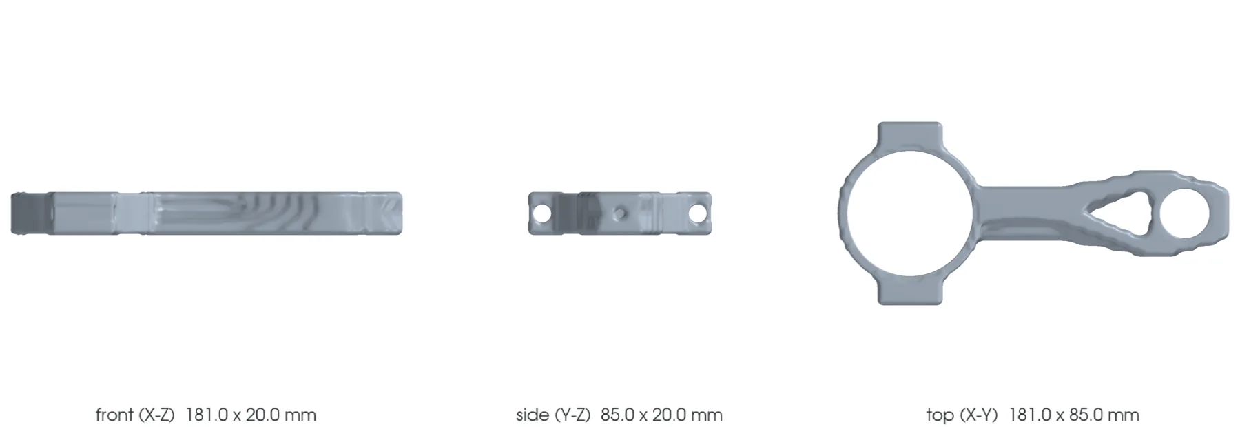
Independent two-open-flange concept to screen an LPBF Ti-6Al-4V connecting rod. The key dimensions come from a PAUTER/TZR record; outer diameters, flanges, cap split and bolt passages remain F0 assumptions with no commercial surface reused.
The design
- Vehicle
- Porsche 993, 1993–1998
- Variants
- 993, 993 Turbo, M64 60 research
- Porsche part numbers
- Not recorded
- Category
- Connecting rod
- Geometry basis
- Mixed
- Preferred process
- Laser powder-bed fusion (metal printing)
- Other candidate processes
- Direct metal laser sintering (metal printing), CNC machining
- Material
- Ti-6Al-4V Grade 5 LPBF for screening; PAUTER titanium alloy unknown
- Material standard
- ASTM F2924 and program-specific connecting rod specification to be contracted
Known limits
- Only the center distance, the two functional diameters, the two widths, the steel mass and the advertised titanium gain come from the PAUTER/TZR record.
- The 78/40 mm outer diameters, the two 10 x 14 mm flanges, the cap and the bolt passages are F0 assumptions.
- The CAD mass of 341.02 g depends on a synthetic shape and a nominal density; it validates neither the PAUTER gain nor the balancing.
- The load case uses a cylinder pressure of 12 MPa, 600 g piston/pin, one third of the rod mass and 100 h, all entirely synthetic.
- LPBF is the preferred process only to study the F0 topology; the production choice remains conditional on comparison with forged/machined steel and conventional titanium.
- Section stresses, the Kt=1.5 factor and Euler replace neither 3D contact, nor bolt preload, nor bearing shells, nor multiaxial fatigue.
- The EOS/TIMET values are ambient and physical comparisons, not hot or fatigue LPBF allowables.
- The full-scale Cecchel study reports fatigue below the conventional reference and requires dedicated qualification.
- The STEP proves only two re-readable BREP solids; it is authorized neither for manufacturing, nor for installation, nor for an engine.
Post-processing it would need
- Powder removal through a fully open topology
- Stress relief and heat treatment qualified for machine, parameters and orientation
- HIP to be decided on defect population and representative fatigue tests
- Separation and machining of the cap, joint face, bolt bores and seats
- Machining and finishing of both bores with defined small-end bushing and bearing shells
- Radiusing, polishing of load paths, end-to-end and set balancing
What a supplier would have to provide
- Traceable powder, machine, parameters, orientation, lot and powder recycling
- Oriented coupons with tensile, toughness, fatigue and representative defects after all post-processing
- Full dimensional analysis of the joint face, center distance, bores, squareness and parallelism
- CT of the body and cap, dye penetrant inspection after machining and roughness check
- Capability evidence on preload, friction, tightening and service life of the selected bolts
- Proof tests then full-scale fatigue with an approved engine envelope before any dyno run
Titanium route
- Alloy
- Ti-6Al-4V Grade 5 candidate only; the alloy of the PAUTER option is not published
- Heat treatment
- EOS stress relief and ductility treatment to be qualified; no recipe is frozen without supplier, orientation and coupons
- Hot isostatic pressing
- To be determined
- CT of the body, cap, fillets and flange transitions
- Full metrology of bores, center distance, joint face, parallelism and squareness
- Dye penetrant inspection after machining and finishing
- Roughness, porosity, alpha case, residual stresses and balancing
- Proof tests and full-scale fatigue with representative bolts, bearing shells and pins
Sources
- TZR Motorsport - manufacturer dimensions of the PAUTER 993/993 Turbo connecting rod · read
Publishes 127.00 mm center distance, 23.01 mm pin, 58.01 +/- 0.003 mm bore, 18.75/19.58 mm widths, 535 g steel mass, 4340 steel, ARP 2000 bolts and a titanium option advertised at -33%. No surface and no titanium grade.
- PorscheFanatics - titanium connecting rods for the 993 engine · read
Precedent for material choice and candidate only; no geometry and no manufacturing specification.
- EOS Titanium Ti64 Grade 5 material data sheet · read
Provides typical LPBF comparison values that depend on machine, orientation and treatment. They are not connecting-rod fatigue allowables.
- TIMETAL 6-4 physical properties · read
Wrought density, modulus, expansion and specific heat are used for physical screening only; they do not constitute an LPBF material card.
- elferclassic - 993 Turbo technical data · read
Documents 100 mm bore, 76.4 mm stroke and 6,720 rpm limiter; cylinder pressure, reciprocating masses and the 100 h cycle remain synthetic.