Engine · 993-ENG-TURBO-OIL-RETURN-LINE-IN625-F0-0001
Turbo oil return line, IN625 F0 concept
ConceptNot authorised until engineering review
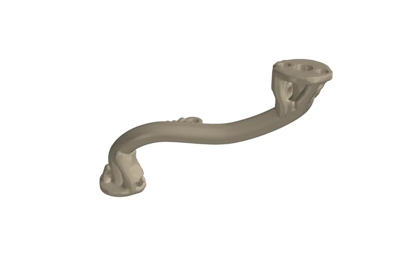
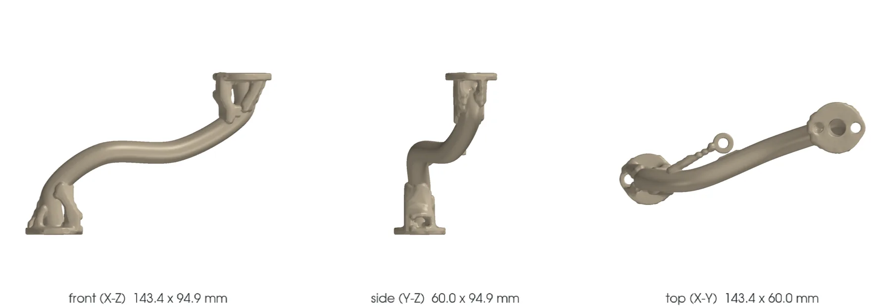
Clean-sheet concept of a left line with an open internal passage and two integrated flanges. PorscheFanatics and Patrick Motorsports confirm the 993 Turbo functional need, but no dimension or material; the entire F0 route remains synthetic.
The design
- Vehicle
- Porsche 993, 1996–1997
- Variants
- 993 Turbo
- Porsche part numbers
- 993 107 125 53, 993 107 126 53, 993 107 338 53, 993 107 339 53
- Category
- Turbocharger oil return line
- Geometry basis
- Estimated
- Preferred process
- Not chosen yet
- Other candidate processes
- Laser powder-bed fusion (metal printing), Direct metal laser sintering (metal printing), sheet_metal, CNC machining
- Material
- EOS NickelAlloy IN625 / UNS N06625 for comparison; commercial material unknown
- Material standard
- ASTM F3055, AMS 7000 or AMS 7001 and a program-specific line specification to be contracted
Known limits
- The name of this record says "return"; plate 202-16 does not establish it. It carries four `oil pipe` references in two positions, without distinguishing feed from return. The attribution remains to be done.
- The sources confirm only the function, the left/right set, 1996-1997 and the final fitting; no dimension is published.
- The F0 left line, its spline, diameters, wall and flanges are entirely synthetic; the right side is absent.
- The theoretical mass depends on the F0 volume and the IN625 density, with no comparison with the commercial part.
- The flows, pressure, temperature, viscosity, minor losses, load and supports are regression inputs.
- Single-phase hydraulics does not represent aerated oil, two-phase drainage, pulsations or the scavenge pump.
- The fully constrained thermal screen fails; the actual compliance and engine-turbo movements are unknown.
- The final-fitting need stated by the supplier is incompatible with a rigid LPBF tube without vehicle metrology.
- The STEP proves only a readable hollow BREP and is authorized neither for manufacturing, nor oil, nor turbo or engine use.
- The circuit counts eleven fluid or retention parts on the same plate: that is where the additive gain lies, and it is not investigated.
- The fittings of an oil line are removed in service. The TITANIUM.md grid explicitly excludes titanium on repeated threading exposed to galling: even without the fire question, this is not a titanium part.
Post-processing it would need
- Orientation with no internal support and recoater strategy to be qualified
- Complete removal of external supports and proof of depowdering
- Stress relief and heat treatment qualified for the thin wall
- HIP to be decided on defects, fatigue, leak-tightness and pressure results
- Machining of faces, bores, seats and datums after compensation
- Controlled internal finishing with no media or debris retention
- Engine-oil cleaning, passivation and cleanliness packaging
What a supplier would have to provide
- Traceable powder, machine, parameters, orientation, supports, lot and recycling
- Oriented thin coupons with tensile, fatigue, oxidation and hot oil compatibility
- Demonstrated capability on a 1.2 mm wall and a 10.3 mm passage with no internal support
- Full CT and borescope with criteria for defects, obstruction and residual powder
- Metrology of both routes, flanges, faces, spacings, clocking and vehicle clearances
- Proof of pressure, leakage, burst, flow, return, thermal cycling and vibration
Sources
- PorscheFanatics - candidate turbo oil return line · read
Identifies the scavenge/return lines as a known weakness and catalogues the Patrick set, without geometry or material.
- Patrick Motorsports - 993 turbo oil return line set · read
Confirms a left/right set, 993 Turbo 1996-1997, pump to tank, anti-backflow shape and mandatory final fitting; no dimension or material.
- EOS NickelAlloy IN625 material data sheet · read
M 290 40 µm comparison values dependent on process and orientation.
- Special Metals - INCONEL alloy 625 · read
Wrought thermal reference used only at F0, not equivalent to LPBF.
- 993 factory catalogue, plate 202-16 Turbocharger · read
Identifies four oil pipe references in two positions, three vent line, two oil collection container and two bracket on the same plate. Establishes neither the feed/return assignment, nor the dimensions, nor the material.