Engine · 993-ENG-INTERCOOLER-END-TANK-ALSI10MG-F0-0001
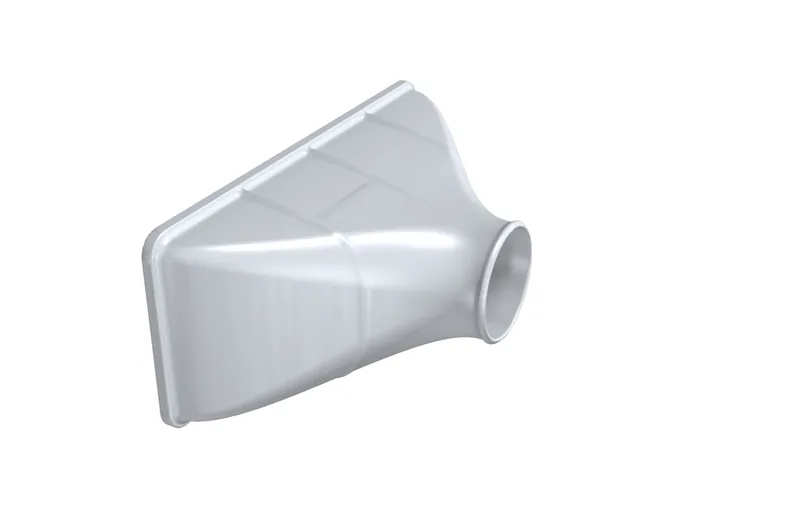
993 Turbo intercooler end tank, AlSi10Mg concept F0
ConceptNot authorised until engineering review
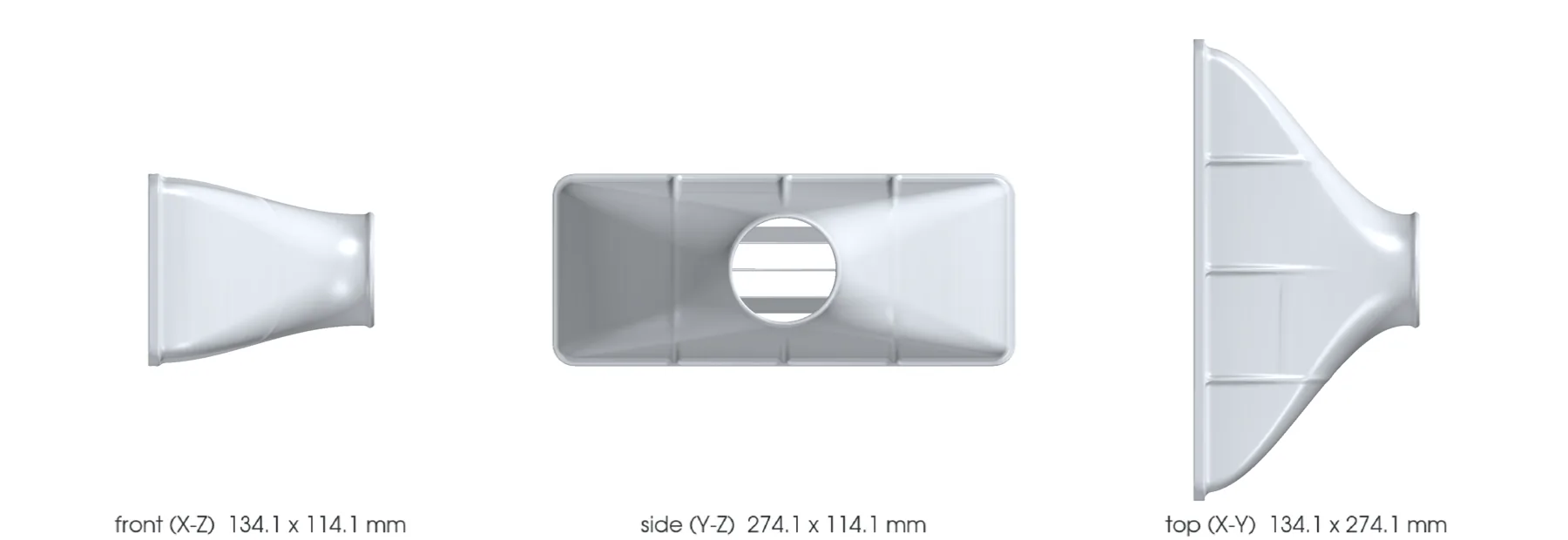
Independent concept of a round-to-rectangular-face transition with three open internal guide vanes, used to screen an LPBF AlSi10Mg end tank. The published overall dimensions bound the F0 but define neither the core orientation nor a compatible geometry.
The design
- Vehicle
- Porsche 993, 1995–1998
- Variants
- 993 Turbo, 993 GT2, M64 60 research
- Porsche part numbers
- Not recorded
- Category
- Charge air intercooler end tank
- Geometry basis
- Mixed
- Preferred process
- Laser powder-bed fusion (metal printing)
- Other candidate processes
- Direct metal laser sintering (metal printing), sheet_metal, casting, CNC machining
- Material
- EOS Aluminium AlSi10Mg for screening; commercial alloy unknown
- Material standard
- DIN EN 1706 EN AC-43000, ASTM F3318 and a program-specific end-tank specification to be contracted
Known limits
- The commercial values describe the complete intercooler and define neither a core face nor an end tank.
- The 260 x 100 mm interpretation, the 120 mm transition, the 2.2 mm wall and the three guide vanes are synthetic.
- The 66 mm connection represents an outer position; the central 68 mm connection and the second core are not modeled.
- The CAD mass of 605.92 g is that of a synthetic end tank and cannot be compared with the 14 kg of the commercial assembly.
- The flow uses 3.6 l, 5,750 rpm, VE 0.95, 1.8 bar absolute, 330 K and porosity 0.65, with no measurement on the vehicle.
- The 487 Pa loss is a sudden-expansion screen, not a CFD with core, turbulence or face uniformity.
- The membrane/panel stresses and thermal bounds replace neither FEA, nor welding/brazing, nor pressure-temperature fatigue.
- The STEP proves only an open BREP and a connected fluid volume; it is authorized neither for manufacture, nor for fitting, nor for an engine.
Post-processing it would need
- Orientation and supports keeping the duct fully open for powder removal
- Heat treatment qualified for machine, parameters, wall and guide vanes
- Build plate cut-off and support removal without damaging the interfaces
- Machining of the core face and the connection after adding the measured machining stock
- Internal finishing of the guide vanes and the transition with controlled roughness
- Assembly to the core by qualified welding or brazing, then proof test and cleaning
What a supplier would have to provide
- Traceable powder, machine, parameters, orientation, batch and recycling
- Capability demonstrated on a 2.2 mm wall and a 1.5 mm guide vane after post-processing
- Supports/recoater/distortion simulation and transition/flange witnesses
- CT of the guide vanes and junctions, then metrology of the walls, face, connection and datums
- Oriented coupons with representative tensile, fatigue, pressure and temperature tests
- Comparison of LPBF, TIG-welded sheet and casting on flow, mass, cost, repairability and service life
Sources
- TA Technix - intercooler for Porsche 911 Turbo 993 · read
Publishes two 260 x 260 x 100 mm cores, 66 mm outer and 68 mm inner connections, 860 mm maximum width, 240 mm height and 690 mm center distance. The orientation and the end tanks are not defined.
- Albert Motorsport - 993 Turbo/GT2 aluminum intercooler · read
Corroborates two 260 x 260 x 100 mm cores and declares a welded aluminum assembly, with no alloy and no end-tank geometry.
- PorscheFanatics - 993 charge-air cooling architecture · read
Identifies the air-to-air function and the charge coolers of the 993 Turbo; no dimension or surface is transferred.
- EOS Aluminium AlSi10Mg material data sheet · read
Reference for a lightweight automotive LPBF material; properties and treatment remain dependent on the exact route.
- elferclassic - German technical data for the 993 Turbo · read
Publishes 3.6 l and 5,750 rpm at peak power; the screening flow, VE, boost and temperature remain synthetic.