Engine · 993-ENG-FAN-STATOR-ALSI10MG-F1-0001
Engine cooling fan guide-vane ring (stator), AlSi10Mg concept F1
ConceptNot authorised until engineering review
Fixed ring of seventeen cambered guide vanes placed 15 mm behind the F1 WE43 impeller, in the same 165/245 mm annulus. The vanes turn the rotor's exit swirl back into pressure. Their angles are designed station by station from the F1 rotor's exit flow, and the vane count is the smallest that keeps the blade-pass interaction tone cut off in the duct. A one-dimensional model on the duty inferred from the rebuild of the original rotor estimates +5.3 % flow over the F1 rotor alone on 6 % less power, and about +10 % over the rebuild rotor on equal power. These are model estimates on visual hypotheses, not measurements.
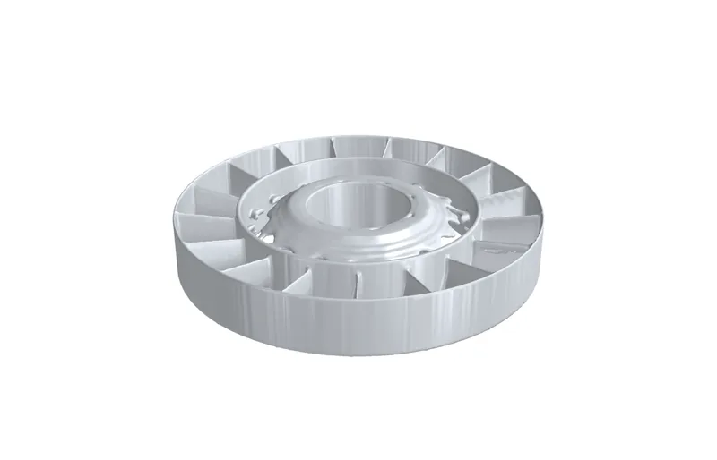
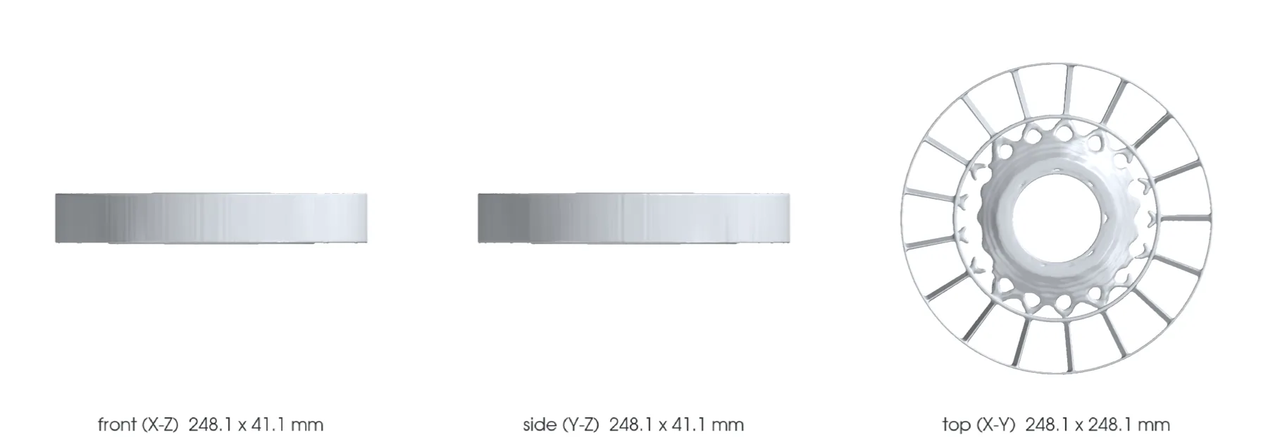
The design
- Vehicle
- Porsche 993, 1994–1998
- Variants
- 993 Carrera fitment to confirm, 964 shared component
- Porsche part numbers
- Not recorded
- Category
- Engine cooling fan stator
- Geometry basis
- Estimated
- Preferred process
- Laser powder-bed fusion (metal printing)
- Other candidate processes
- casting, CNC machining
- Material
- EOS Aluminium AlSi10Mg T6 for comparison
- Material standard
- DIN EN 1706 EN AC-43000 and ASTM F3318 for the candidate; program-specific specification to be contracted
Known limits
- The rotor follows a visual rebuild, and the speed and engine resistance it is designed against are inferred, not measured.
- The gain is a one-dimensional model estimate in a bellmouth housing: +5.3 % flow over the F1 rotor alone, on a duty inferred from the visual rebuild of the original rotor.
- The first vane mode lies between 2,876 Hz (pinned) and 6,520 Hz (clamped); it clears blade-pass and twice blade-pass at nominal and overspeed by 22 %.
- The tone screen is a thin-annulus estimate; one second-harmonic interaction mode stays cut on.
- Vane and ring blockage, wakes and the upstream housing spokes are not modelled.
- The F0 housing has no seat for the ring; mounting, alternator clearance and tinware interface are undefined.
- No manufacture, installation or start-up is authorized.
Post-processing it would need
- Print flat on the ring face with the inner web on the plate; vanes at 5 to 8 degrees of stagger stand nearly vertical
- Stress relief then T6, distortion of the thin outer ring monitored
- Smooth vane leading edges and ring bores
- Machine the ring faces and the bore to the housing F1 seat once it exists
What a supplier would have to provide
- Traceable machine, parameters, orientation, powder and batch
- Metrology of vane angles at hub, mid and tip, ring roundness and faces
- Tap test or modal survey of the vanes to fix the real end fixity
Sources
- EOS Aluminium AlSi10Mg material data sheet · read
Generic comparison values, as for the F0 housing and impeller.