Research & design · Porsche 993 Turbo · M64.60
F1 concept · printing not authorised
Porsche 993 Turbo fan.
Twisted blades, guide vanes.
We rebuilt the Turbo cooling fan rotor from its part references, then redesigned it: eleven twisted airfoil blades in magnesium, followed by a fixed ring of guide vanes. A one-dimensional model says where the gain comes from. Nothing has been printed, measured or fitted.
Project status as of
01 / The rotor
Same cup, new blades
F1 keeps the envelope and interfaces of our rebuild of the original rotor: the cup that wraps the alternator end, its twelve windows, the bolt circle and the bore. Only the blades and the alloy change. The original’s flat, constant-pitch plates become twisted airfoils whose angle follows the air from hub to tip.
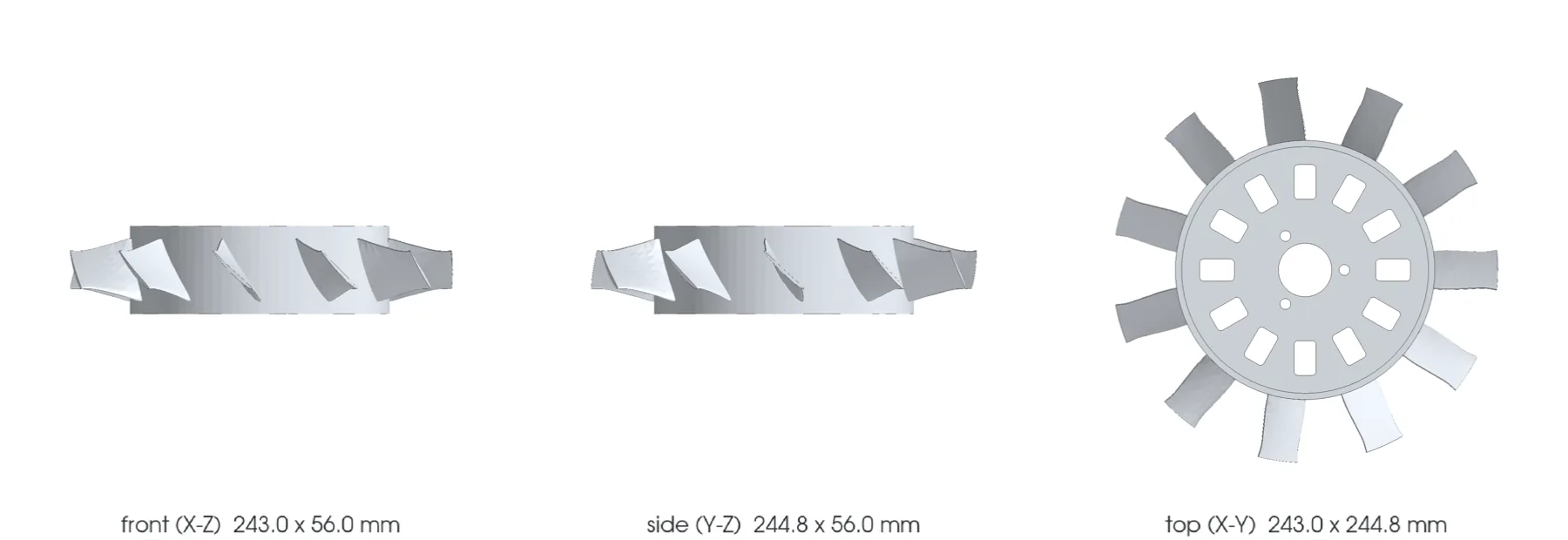
| Rebuild of the original | F1 | |
|---|---|---|
| Diameter | 245 mm | 245 mm |
| Cup | 165 mm, 56 mm deep | same |
| Windows, bolt holes, bore | 12 windows, 3 × Ø6.8 mm, Ø34 mm bore | same |
| Blades | 11 flat plates at a constant 48° pitch | 11 twisted airfoils, 32° → 46° stagger |
| Mass in WE43 magnesium | 524 g | 421 g |
Masses compare the two shapes in the same alloy. FVD lists the real rotor at 0.9 kg without naming its material, which suggests our visual rebuild carries less material than the original.
02 / The model
The blades help a little. The guide vanes help more.
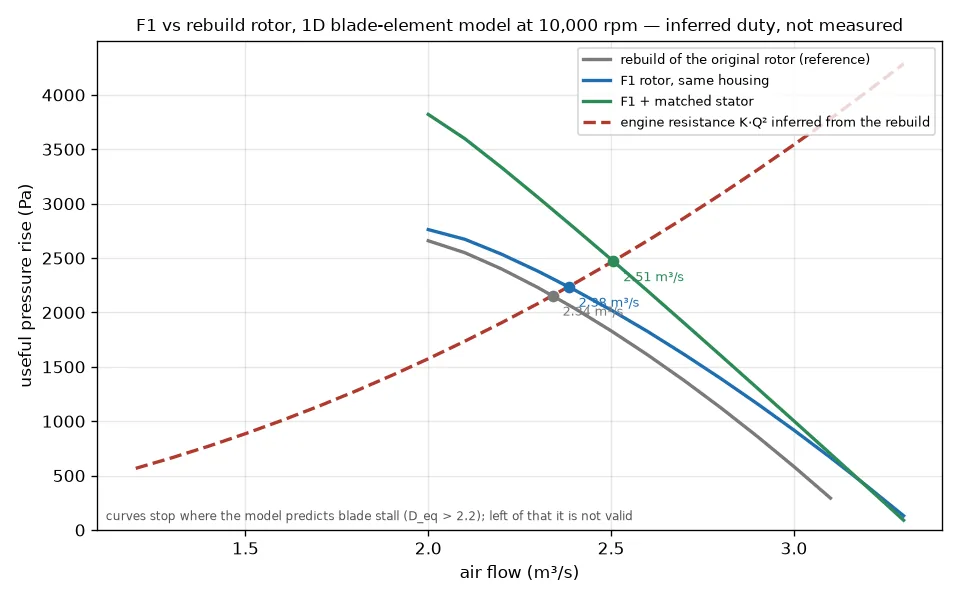
No 993 fan map, pulley ratio or engine resistance is published. The model therefore infers the duty from the rebuilt rotor: about 2.34 m³/s at 10,000 fan rpm against an engine resistance that rises with the square of the flow. Both rotors then run through the same blade-element model.
| At 10,000 rpm | Airflow | vs rebuild | Shaft power | Efficiency |
|---|---|---|---|---|
| Rebuild of the original | 2.34 m³/s | — | 9.28 kW | 0.54 |
| F1 rotor, same housing | 2.38 m³/s | +1.9 % | 9.25 kW | 0.58 |
| F1 rotor + guide-vane ring | 2.51 m³/s | +7.1 % | 8.72 kW | 0.71 |
Where the gain comes from
The airfoils cut the blade losses by more than half, but the 3.5 mm gap at the blade tips and the swirl left in the air cost more, and they are the same for both rotors. So the F1 rotor alone moves only 1.9 % more air.
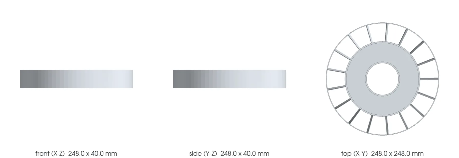
The guide-vane ring turns that swirl back into pressure. With it, F1 moves 7.1 % more air on 6 % less power. Closing the tip gap with a machined land in the housing is the next lever.
How much it depends on the guesses
At the original rotor’s power, F1 stays ahead in every case tried, by about 1 to 4 %. At the same speed the result depends on the original’s blade pitch, which is a visual estimate: with 43° instead of 48° F1 gains 11.7 %, with 53° it loses 5.2 %. Measuring that one angle on a real rotor matters more than any further modelling.
03 / The material
Magnesium is lighter, and harder to live with
In WE43 magnesium the F1 rotor weighs 421 g, against 611 g for the same shape in AlSi10Mg aluminium, and stores a third less energy at overspeed. Hand calculations put the blade roots and cup well inside the material’s strength at 12,000 rpm, with the first blade vibration mode about 35 % above the housing spokes’ excitation.
The cost: at 150 °C the bolted joint to the bearing hub needs steel inserts or creep-rated washers. Magnesium also corrodes against the steel bolts and aluminium housing, so it needs a coating and isolation. Few service bureaus can print it, and its published strength comes from a single laboratory’s room-temperature samples.
04 / The print simulation
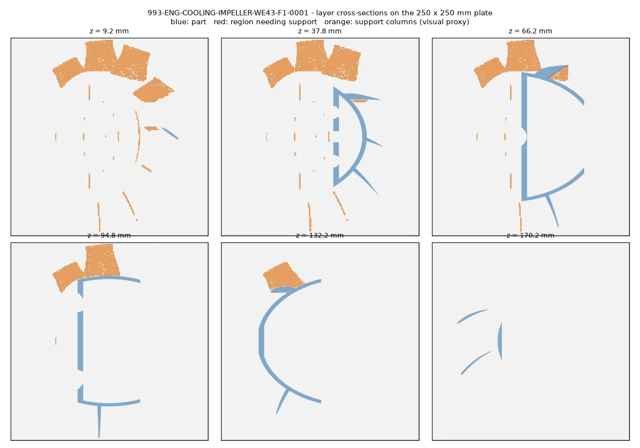
6,286 layers, simulated
The geometry was sliced over its full height at 30 µm on the build volume of an EOS M 290 metal printer. The orientation with the least downward-facing area is a 45° tilt, not flat on the web. The video shows the part growing layer by layer, with the support it would need in orange.
05 / The system
The alternator is part of the problem
The fan works with its housing, the alternator’s internal passages and the drive system. Optimising blades alone cannot establish how much air reaches the engine.
The PMB / Classic Retrofit 240 A is the selected target. The supplier recommends a serpentine belt with a tensioner, and recommends its 175 A unit for standard double-pulley and RS arrangements.
A specific variant
The working target is the 993 Turbo M64.60. The Carrera rotor 96410601531, photographs of a 175 A alternator and dimensions of a 997 alternator are not transferred to the Turbo / 240 A model.
| Component | Reference | Status |
|---|---|---|
| Turbo impeller | 96410601522 | Visually rebuilt; F1 redesign keeps its cup, windows, bolt circle and bore. |
| Turbo housing | 99310666750 | Identified; inner profile and stationary vanes still need measurement. |
| Bearing hub | 96410605131 | Modelled separately; suppliers disagree on Turbo compatibility. |
| Alternator | PMB / Classic Retrofit 240 A | Selected target; dimensioned interfaces still required. |
| Rear cone | 93060304101 | Identified; geometry still to be reconstructed. |
| Auxiliary impeller | 92860304501 | Identified in the original assembly; adaptation to be checked. |
FVD lists hub 96410605131 as Turbo-compatible, while Patrick Motorsports excludes that variant. This discrepancy remains unresolved; our reconstruction does not establish compatibility.
06 / The route
From references to a flow rig
Completed
Document
14 sources and all 25 positions in the Porsche PET illustration recorded. Carrera and Turbo variants are kept separate.
Visual rebuild completed
Rebuild the original
An 11-blade rotor, 165 mm cup, 12 windows and separate hub. Apart from the blade and window counts and the envelope, every dimension is a visual assumption.
1D model and print simulation completed
Redesign
Five organic shapes were tried first, then the F1 rotor and its matched guide-vane ring. F1 is the current design.
To start
Assemble & validate
Measured housing and PMB 240 A interfaces, rotating CFD, structural analysis with the bolted joint, then a flow rig.
Next gates
- Measure the original rotor’s blade pitch, chord and cup depth. The comparison rests on them.
- Account for the alternator air passing through the cup windows, which the model does not see.
- Design the housing land over the blade tips, the guide-vane ring mounting and the inlet.
- Run rotating CFD of the original and F1 in the same domain, to check the 1D ranking.
- Analyse the bolted joint, the blade vibration modes and fatigue with WE43 allowables.
- Prepare a supplier build file, coating, balancing, a contained overspeed test and a flow rig.
Earlier: the organic blade trials (September 2026)
Before F1, five organic candidates added sweep, twist and curved camber to the rebuilt cup. Six isolated-rotor CFD pilots, centrifugal solves and bulk thermal print trials were run on them. Every CFD pilot failed its extended mesh and convergence checks, so no candidate was carried forward on airflow; F1 replaced them with blades worked out from the rebuilt rotor in a one-dimensional model.
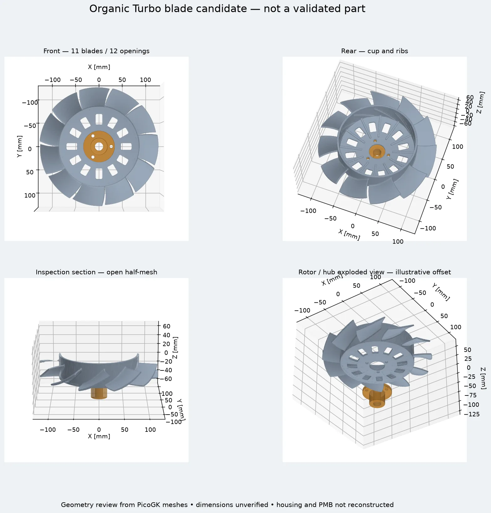
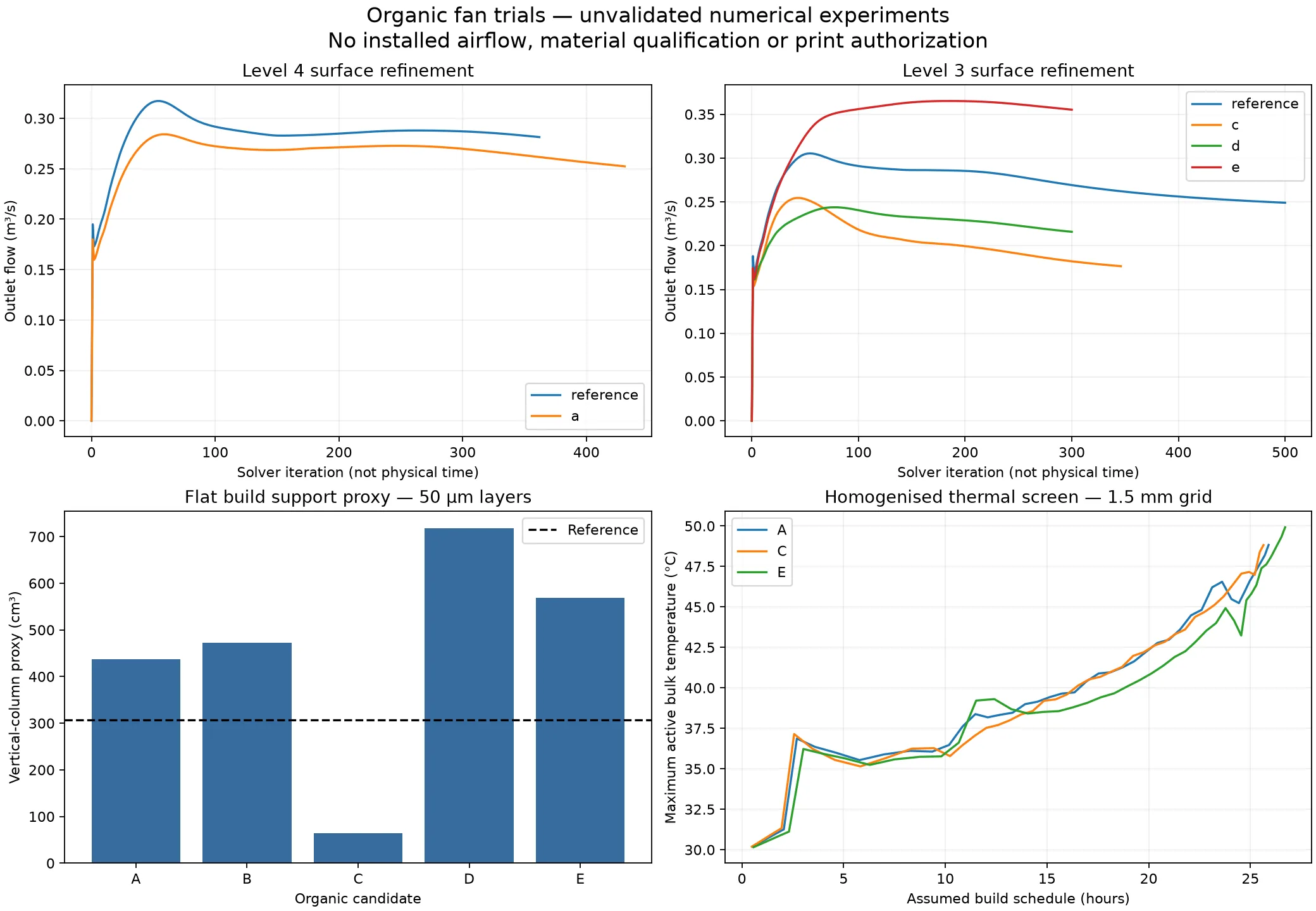
Current status: F1 rotor and guide-vane ring modelled · print simulated · airflow, strength and PMB interfaces unvalidated · manufacture, rotation, installation and engine operation not authorised.
07 / The evidence
Where the numbers come from
The figures, pictures and video on this page are copied from our engineering repository at revision dcecbe1 (8 October 2026). That repository is private, so its files are summarised here rather than linked. The public references behind the rebuild are below.
Primary references
- Porsche PET 993 — illustration 105-00, PDF pages 77–78: parts and variants.
- FVD — Turbo rotor 96410601522: product views, 0.9 kg listed mass and commercial envelope without tolerances.
- WOSP — LMA339 / LMA498 spacer instructions: stacks by configuration; exact PMB applicability still to be confirmed.
- Hyer et al. (2020), laser powder-bed fusion of WE43: the single-laboratory strength figures and 30 µm layer used for the magnesium route.
Questions or a measured original rotor to share? Ask in the forum or send a correction with its source.