Engine · 993-ENG-COOLING-IMPELLER-WE43-F1-0001
Engine cooling fan impeller, WE43 magnesium concept F1 redesigned from the Turbo rotor rebuild
ConceptNot authorised until engineering review
Improved variant of the 993 Turbo cooling fan rotor, drawn from the repository's visual rebuild of the original. It keeps the rebuild's 245 mm envelope, its 165 mm cup 56 mm deep that wraps the alternator end, the cup's twelve windows, three bolt holes and bore, eleven blades and no shroud. It replaces the rebuild's constant-pitch cambered plates with twisted airfoil blades designed from velocity triangles, and moves to LPBF WE43 magnesium. A one-dimensional blade-element model with radial equilibrium, on a duty inferred from the rebuild, estimates about 2 % more air than the rebuild rotor on the same shaft power, and about 9 % with a matched stator. These are model estimates on visual hypotheses, not measurements and not a comparison with the Porsche part.
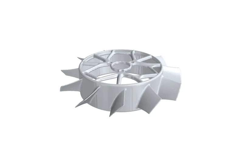
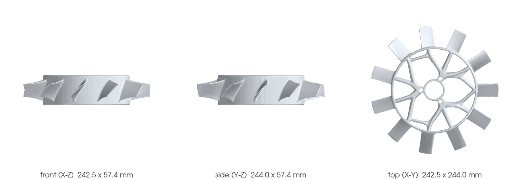
The design
- Vehicle
- Porsche 993, 1994–1998
- Variants
- 993 Turbo, M64 60 research
- Porsche part numbers
- 96410601522
- Category
- Engine cooling fan impeller
- Geometry basis
- Estimated
- Preferred process
- Laser powder-bed fusion (metal printing)
- Other candidate processes
- CNC machining, casting
- Material
- WE43 LPBF, solutionized and aged, for comparison; Scalmalloy and AlSi10Mg screened as alternatives
- Material standard
- ASTM B80/B107 WE43 composition reference only; program-specific LPBF, rotating, HCF, balance and overspeed specification to be contracted
Known limits
- The separate roll_y_45 polymer or carbon-fiber-filled thermoplastic export is a static mockup only; printer, material grade, supports and slicing parameters remain unspecified. The WE43 thermal study does not apply to that mockup.
- The 2026-10-12 LPBF study solves uncalibrated bulk heat conduction on the concept CAD with assumed supports and conventional WE43 constants; melt pools, residual stress, distortion and print success are not predicted.
- The rebuild of the original rotor is a visual reconstruction: blade and window counts are observed, the 48 degree pitch, chords, cup depth and walls are hypotheses.
- The duty is inferred from the rebuild (its best-efficiency point at 10,000 fan rpm in a bellmouth housing: 2.34 m3/s at 2,155 Pa); no 993 fan map, pulley ratio or engine resistance is measured.
- The flow gains come from a one-dimensional blade-element model with simple radial equilibrium, not CFD or a rig test; the alternator air through the cup windows is not modelled.
- On the same shaft power F1 moves about 2 % more air than the rebuild rotor and keeps its stall margin; the same-speed gain ranges from -5 % to +12 % when the rebuild's pitch is varied from 53 to 43 degrees.
- Both rotors lose more to the 3.5 mm tip gap and to exit swirl than to blade profile; the matched stator (about +9 % at equal power) and a housing land over the tips are the larger levers, and belong to a future housing.
- WE43 data are single-laboratory room-temperature coupons plus generic values; no hot, HCF or notched allowable.
- The fully constrained thermal screen fails for WE43; the bolted joint to the bearing hub needs inserts or creep-rated washers.
- The beam estimate of the open-blade first mode (about 1,350 Hz) is superseded by the 2026-10-13 FE screen (gmsh C3D10 + CalculiX, one 4 mm mesh, hub joint idealised as clamped or as a fixed bore): the first blade-bending family sits at 1,890-2,530 Hz, the lowest modes are cup/web modes (344-525 Hz at rest), and the engineering screen's modal pass does not cover them.
- In that FE screen the 17-vane stator order meets the five-nodal-diameter blade mode at about 7,600 rpm, inside the nominal range, and the spokes' 12th-order harmonic meets one-nodal-diameter modes at about 1,700-2,600 and 11,400 rpm; forcing and damping are not computed, so these are crossings to design around, not predicted failures.
- The same FE screen puts the 12,000 rpm peak at 92-96 MPa (yield / peak 2.3-2.4) at the unfilleted blade-root/rim corner, far above the beam screen's 11-47 MPa; mesh independence is not demonstrated and that corner needs a fillet before any stress figure is quoted.
- An earlier F1 revision (120 mm hub, shroud, 248 mm) was a generic fan that did not keep the original cup or alternator space; it is superseded.
- The flat-fan sizing study F2 is a separate shrouded rotor family on F0-scaled duties; its findings do not describe this upright rotor.
Post-processing it would need
- Flat build_z is the preferred next study candidate after the thermal comparison; roll_y_45 is retained as a comparison; thermal anchoring, support topology and removal access require supplier review
- Solutionizing and ageing, distortion monitored
- HIP to be decided by the HCF/defect card
- Steel inserts or creep-rated washers at the three bolt holes, machined web faces and bore
- Conversion or PEO coating and galvanic isolation from steel and aluminium neighbours
- Two-plane dynamic balancing in the final condition
What a supplier would have to provide
- Inert, magnesium-rated LPBF machine with powder handling and fire procedure
- Traceable machine, parameters, orientation, supports, powder, recycling and batch
- Oriented coupons with tensile, HCF and hot corrosion tests
- Full CT and metallography with zoned defect criteria
- Metrology of cup, web, bore, bolt holes, runout, blades and mass
- Proof of balance, overspeed, vibration, flow, containment and endurance
Sources
- FVD - Porsche 965/993 Turbo cooling fan rotor 964 106 015 22 · read
The original rotor this F1 redesigns: photographs (11 blades, 12 windows counted from them) and a declared 245 x 245 x 87 mm, 0.9 kg envelope. Linked, never copied.
- PorscheFanatics - 964/993 engine cooling fan impeller · read
Identifies Porsche AG part 964 106 015 31 for 964/993 with no geometry and no material.
- Additive manufacturing of dense WE43 Mg alloy by laser powder bed fusion (Hyer et al., 2020) · read
Academic LPBF WE43 coupon data: yield 219 MPa after solutionizing and ageing.
- AZoM - Magnesium Elektron WE43 alloy properties · read
Density 1.8 g/cm3, expansion 26.7 um/m/C, service to 300 C for conventional WE43.
- APWORKS - Scalmalloy · read
Comparison alloy: yield 480 MPa, UTS 520 MPa, 13 %.
- EOS Aluminium AlSi10Mg material data sheet · read
F0 comparison alloy, kept for continuity.
- Ferdinand magazine - EB Motorsport flat fan kit · read
Flat-fan sizing study context: 1.5 hp at 4,000 and 32 hp at 12,000 fan rpm.
- Jim Torres Racing - reproduction 935 flat fan · read
Flat-fan layout context: aluminium stator, oil-fed gear drive, external alternator.