Redesign study · Porsche 993 Turbo · part 993 115 021 53
V6f provisional study · R9 and V5 archives
The Turbo engine carrier,
in titanium.
The engine carrier holds the back of the 993 Turbo's engine to the body through a separate bracket and two mounts. V6f corrects the V5 study's hypothetical bracket mismatch and stays below the nominal 1.2 kg ceiling. Its structural results remain rejected; measured Porsche interfaces and an engine-ready part are still missing.
V6f reviewed through · R9 retained from 6 October
New / V6f correction
The assumed bracket now aligns
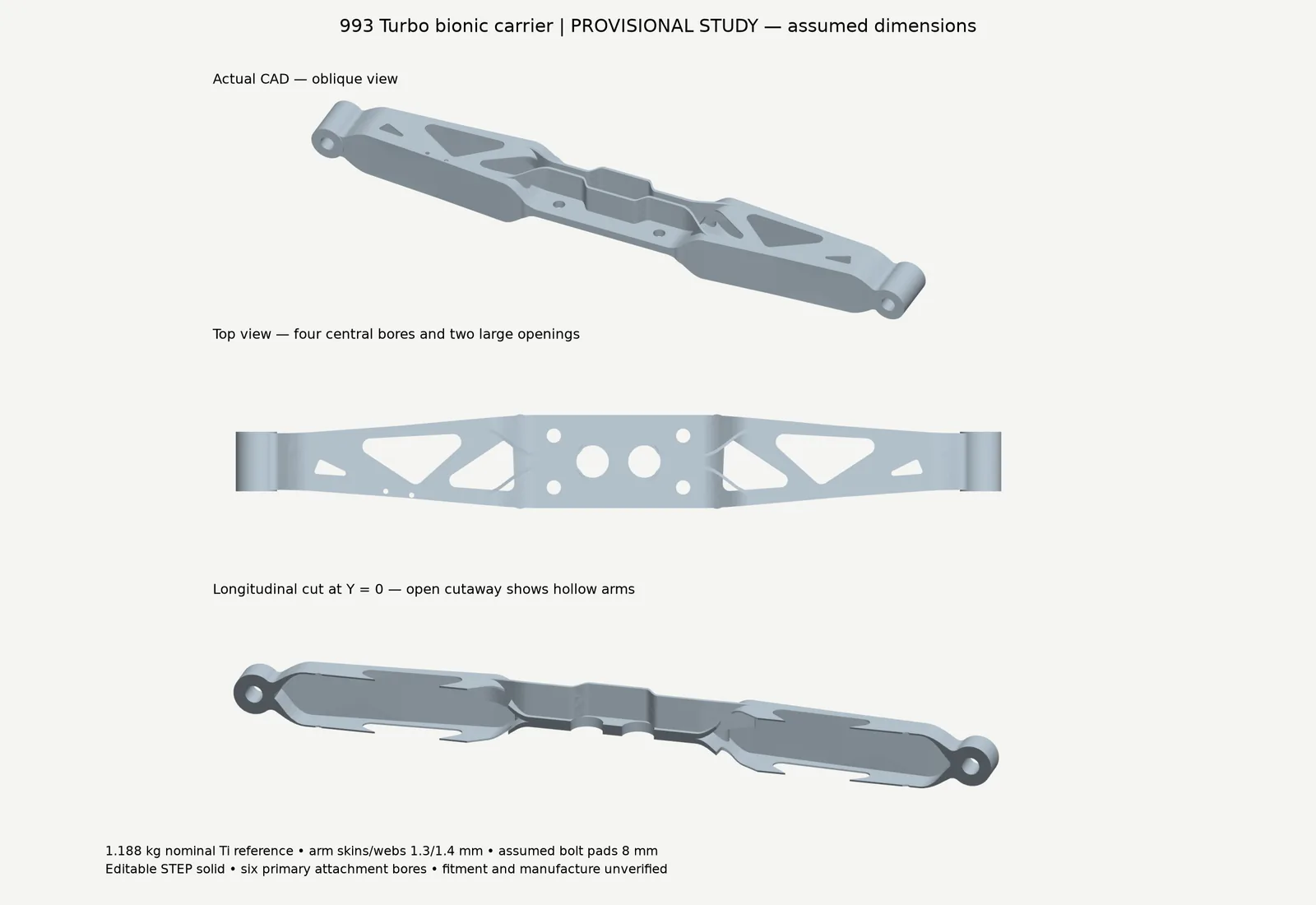
The load path is engine → separate bracket → four central attachments → carrier arms → two end mounts → body. Independent CAD inspection confirms alignment with the frozen hypothetical bracket, preserves the end interfaces and checks tool access. The real bracket-to-engine interfaces, bolt grip, thread engagement and installed position remain unknown.
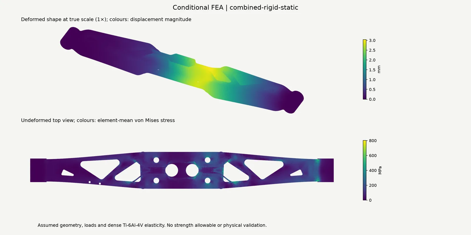
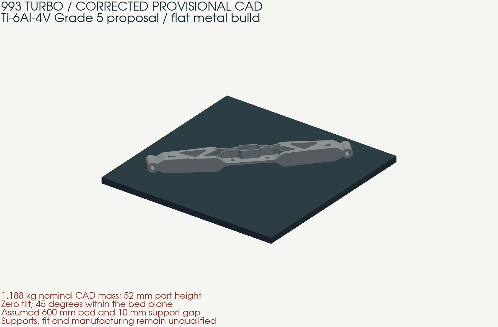
All 866 nonempty 60 µm contours close. A fresh uniform-contraction control gives about 0.304 mm registered release deformation; it is not a staged build-distortion prediction. V5's staged results are not transferred to V6f. Machine parameters, metal supports, heat treatment, machining and inspection remain unqualified.
A separate native BCC trial is rejected for its 1.280 kg calculated mass and three connected components. V6f retains the editable CAD master; the lattice is not an accepted replacement.
V6f status: provisional geometry · structural acceptance rejected · manufacturing and engine support not authorised.
V6f evidence reviewed at engineering revision e697398. Earlier studies below retain their own results.
Archive / Separate V5 geometry
Grade 5 titanium, lying flat
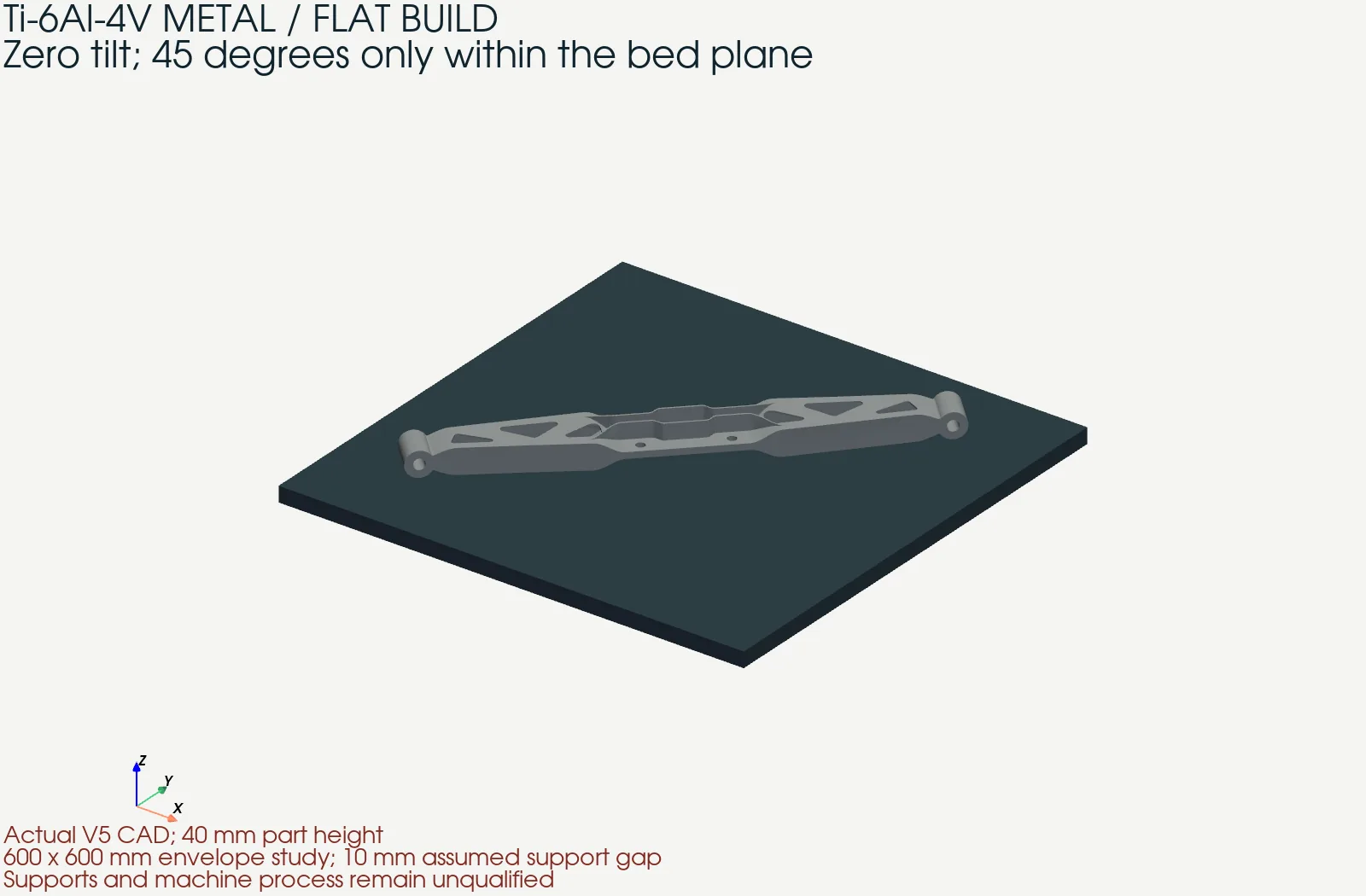
The proposed metal is Ti-6Al-4V Grade 5. A 400 or 450 mm square bed cannot fit the chosen flat placement; a 600 mm study envelope fits geometrically. No supplier, build recipe or support design is qualified for that larger machine. Original fastener geometry, thread engagement, contact and installation clearances still require measurements.
The flat transform preserves the same V5 solid. A 60 µm contour study closes all 666 nonempty part slices; a finer integration audit reduces the volume discrepancy, without changing the proposed study layer height or creating a machine job file.
V5 CAD and flat-build evidence reviewed at engineering revision e697398. The frozen R9 results below retain their earlier identity.
01 / The part
Archived R9: ribs and one corrected corner
The design keeps the carrier's two ends and opens the body between them into ribs around a central blade. R9 differs from R8 by one change: a wider blend where the lower opening meets the cap, a corner where R8 showed a sharp local stress peak.
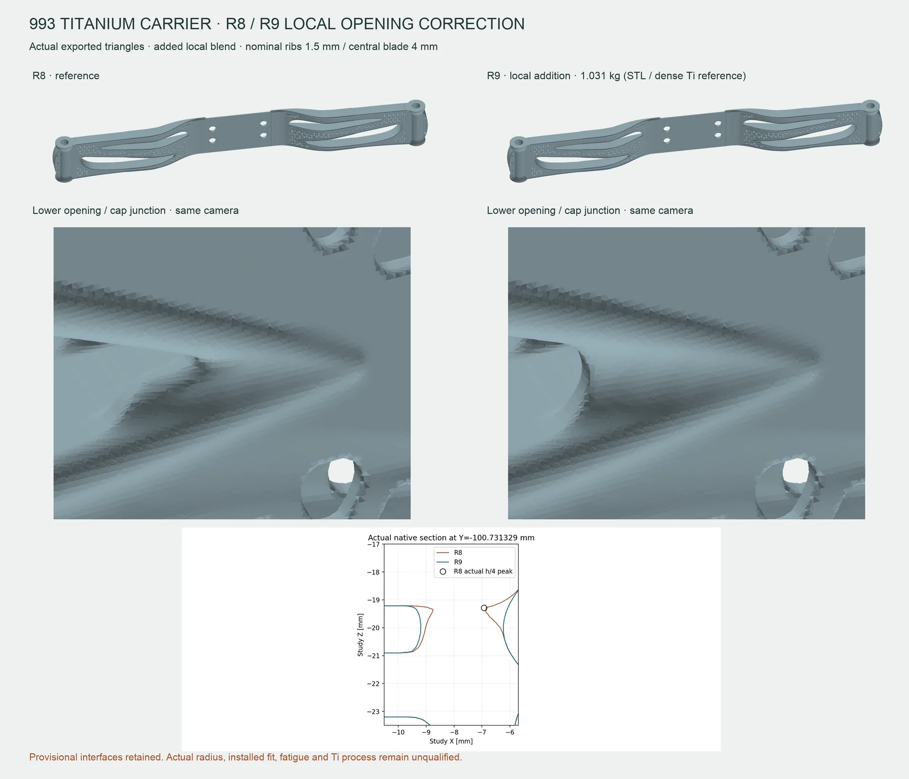
The original carrier's alloy, construction, dimensions and any cracking mechanism are not verified. Read the factory reference and what is known about it on the 993 115 021 53 record. The concern that carriers crack above about 700 hp is an owner concern, not a demonstrated threshold: engine power alone does not set the carrier's loads.
02 / The calculation
One assumed load, two revisions
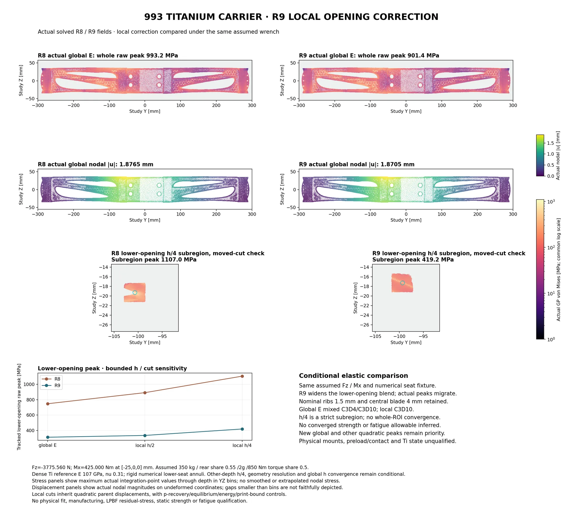
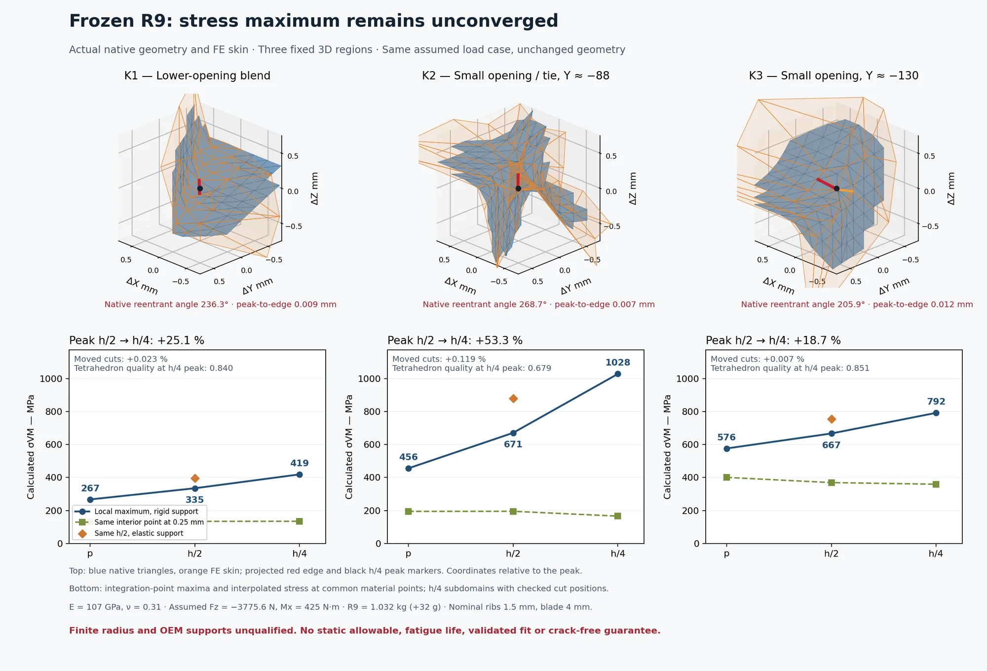
Both revisions carry the same illustrative load: a 350 kg engine with 55 % of it at the rear, an effective 2 g vertically, and half of an 850 N·m engine torque. That gives a vertical force of 3,776 N and a moment of 425 N·m. These are assumptions, not measured loads.
| Fixed region of R9 | Base mesh, MPa | Half size, MPa | Quarter size, MPa | Last refinement |
|---|---|---|---|---|
| K1, lower-opening blend | 267 | 335 | 419 | +25.1 % |
| K2, small opening and tie | 456 | 671 | 1,028 | +53.3 % |
| K3, small opening | 576 | 667 | 792 | +18.7 % |
03 / The route
What would have to come next
- Measure the real carrier and its mounts: interfaces, alloy, wall thickness, and how cracked carriers actually fail.
- Replace the assumed load with measured or documented engine and chassis loads, including vibration.
- Give every corner a real radius and converge the stresses; then check static strength, fatigue and the bolted joints.
- Only then a titanium printing route, with its own defects, heat treatment and qualification, and a physical test.
A later revision, R10, has not been admitted: its exported mesh fails one of the geometry checks. The project's earlier steps were a first concept on 28 August and a revision prepared with the help of our local engineering model on 1 October.
Archived R9 status: concept R9 · provisional interfaces · stress unconverged · no static, fatigue or crack-free claim · safety-critical, not authorised for manufacture or fitting.
04 / The evidence
Where this comes from
The renders and results are our own, from the engineering repository at revision f8499c8; their publication was approved on 6 October 2026. They contain no factory catalogue photographs. Material values are a dense Ti-6Al-4V reference (E 107 GPa), not a qualified printed-titanium card.
Part design record · Factory reference · All projects · Send a correction with its source