Engine · 993-ENG-TURBO-HEAT-SHIELD-IN625-F0-0001
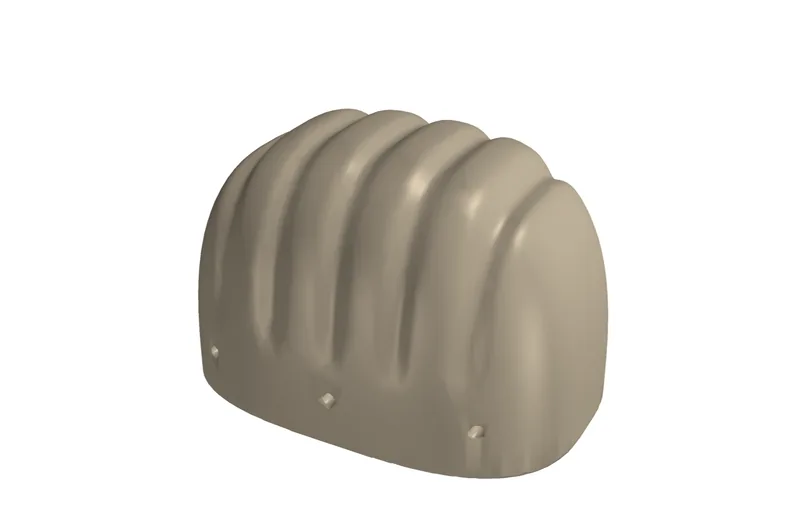
993 left turbo heat shield cover, F0 IN625 concept
ConceptFunctional part
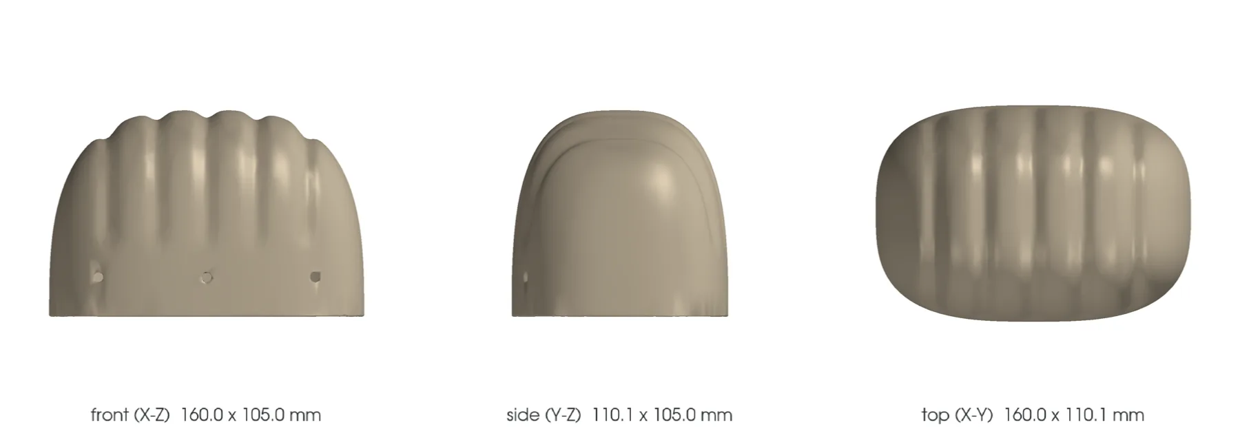
Independent concept of an open shell with integrated bosses for screening an LPBF remanufacture in IN625. PorscheFanatics confirms the PET identity; FVD publishes only the envelope and mass of the left-hand cover 993 123 113 51.
The design
- Vehicle
- Porsche 993, 1995–1998
- Variants
- 993 Turbo, 993 GT2
- Porsche part numbers
- 99312311351
- Category
- Turbocharger heat protection
- Geometry basis
- Mixed
- Preferred process
- Not chosen yet
- Other candidate processes
- Laser powder-bed fusion (metal printing), Direct metal laser sintering (metal printing), sheet_metal
- Material
- EOS NickelAlloy IN625 / UNS N06625, screening; OEM material unknown
- Material standard
- ASTM F3055, AMS 7000 or AMS 7001 to be contracted according to the selected process
Known limits
- Only the 160 x 110 x 105 mm envelope comes from FVD; profile, wall, bosses and holes are hypothetical.
- The F0 mass of 325.58 g exceeds the published 230 g by 41.6%; the commercial material is unknown and no validation by mass is possible.
- The temperatures, emissivity, view factor, force and support conditions are synthetic.
- The calculation ignores convection, real turbo geometry, shell curvature, contact, vibration, thermal fatigue, oxidation and creep.
- The STEP proves only a computable BREP within the envelope and must not be manufactured for fitment.
Post-processing it would need
- Support removal with full opening of the shell
- Stress relief qualified for the machine and parameters
- Removal from the build plate and controlled straightening of the thin wall
- Machining or boring of the interfaces after adding machining allowances
- Deburring and edge finishing
- Thermal coating to be decided after testing
What a supplier would have to provide
- Traceable powder, machine, parameters, orientation, lot and recycling
- Demonstrated capability on a 0.8 mm wall and representative coupons
- Dimensional inspection of the envelope, edges and interfaces
- CT or radiography of the bosses and penetrant testing after finishing
- Roughness, porosity, residual stresses and distortion specified by contract
- Thermal, vibration and cyclic tests before fitment
Sources
- PorscheFanatics - PET transcription of the 993 Turbo groups · read
Confirms 993 123 113 51 in turbo group 202-16, with no dimension and no CAD surface.
- FVD - left heat shield cover 99312311351 · read
FVD declares 160 x 110 x 105 mm, 0.23 kg and the 993 Turbo/GT2 applications. The F0 topology and interfaces are independent.
- EOS NickelAlloy IN625 material data sheet · read
M 290 40 µm screening values, dependent on orientation and post-processing.
- Special Metals - INCONEL alloy 625 · read
Wrought thermal properties used as references, never as an LPBF allowables map.