Lighting · 993-ELEC-HEADLAMP-SPRING-HOOK-F0-0001
Headlamp spring hook repair, aluminium F0 concept
ConceptFunctional part
Independent hollow hook concept for studying an additive repair of the lamp spring mount of a 993 headlamp. A commercial offer proves that metal printing is really used for this function, but no public dimension allows this F0 to be presented as its copy or as a fitted part.
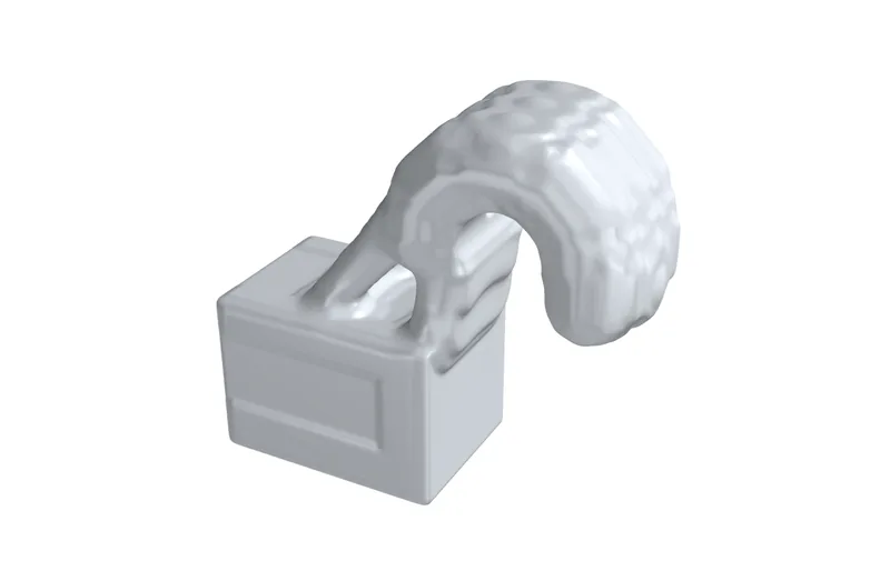
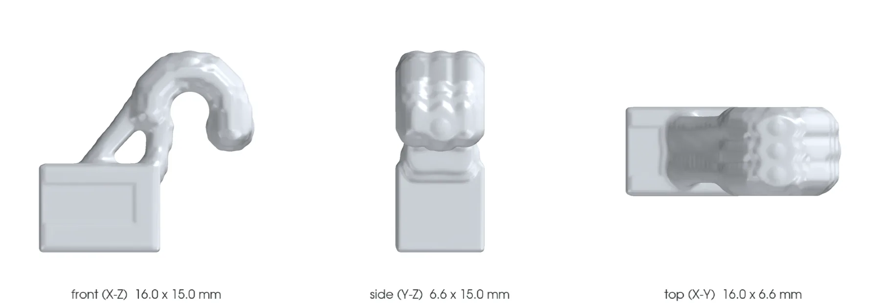
The design
- Vehicle
- Porsche 993, 1994–1998
- Variants
- 993 headlamp application declared by vendor to confirm
- Porsche part numbers
- Not recorded
- Category
- Lighting repair
- Geometry basis
- Estimated
- Preferred process
- Laser powder-bed fusion (metal printing)
- Other candidate processes
- CNC machining
- Material
- EOS Aluminium AlSi10Mg / AlSi10Mg_FlexM291 2.01 / 30 µm, screening candidate not attributed to the commercial part
- Material standard
- DIN EN 1706 EN AC-43000 and ASTM F3318-18 per the EOS data sheet; supplier specification to be contracted
Known limits
- All F0 dimensions are independent design variables, not measurements of the product or of the headlamp.
- The 30 N and 100 K case is synthetic and does not represent a measured 993 load or temperature.
- The elastic check uses a room-temperature AlSi10Mg card and ignores LPBF defects, notches, fatigue and temperature.
- The fine CalculiX thermal p95 of 141.90 MPa is a result on a synthetic gradient and fixed support; the local maximum of 303.47 MPa and the lack of hot strength data block any conclusion.
- The ovphysx witness proves the loading and rigid contact of the USD mesh, not the spring function or the headlamp assembly.
- The bonded joint has no allowable strength until adhesive, preparation, clearance and thermal cycle are qualified.
- The STEP proves only a computable geometry; it must be neither printed for fitting nor installed in a headlamp.
Post-processing it would need
- Removal of supports outside the cavity
- Controlled deburring of the spring groove
- Heat treatment tied to the machine and the parameter set
- Finishing of the bonding surface without rounding the future datums
What a supplier would have to provide
- Traceable powder, machine, orientation and batch
- Witness coupon in the critical orientation of the arm
- CT or radiography of the root and dimensional inspection
- Roughness report inside the groove
- Thermal, vibration and retention tests before any vehicle use
Sources
- Roadster-Fashion - printed headlamp spring hook for 993 · read
The manufacturer claims 3D manufacture in aluminum or stainless steel, fitting onto the remaining hook by high-temperature bonding, and an M3 option if the base is broken. The images serve only to understand the function; no dimension or geometry is copied.
- EOS Aluminium AlSi10Mg for EOS M 290 - 30 micrometre process data sheet · read
Public TRL 9 route AlSi10Mg_FlexM291 2.01 / EOS M 290 / 30 µm and as-built coupon properties. Scan paths, supports, part allowables and a full hot-property card remain absent.